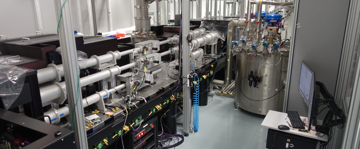
The HiLASE 100J/10 HZ laser system (‘Bivoj) was built at the Central Laser Facility (CLF) in UK. Construction began in April 2013 and was completed in October 2015. After shipment from the CLF, the Bivoj laser system was rebuilt and recommissioned at the HiLASE Centre over a 12 month period by a collaborative team from the CLF and HiLASE. This involved 17 separate visits to HiLASE Centre by 15 team members from the CLF (a total of ~140 working days).
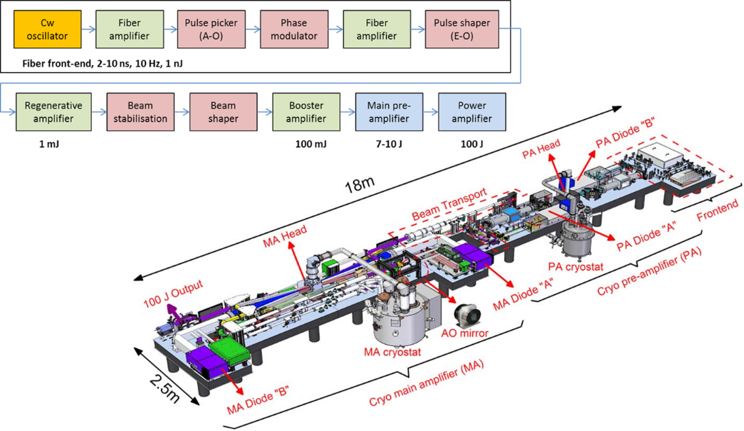
The HiLASE Centre 100 laser (‘Bivoj’) is based on a master oscillator power amplifier (MOPA) architecture incorporating multiple amplification stages, as shown schematically in Figure 1. A front end provides temporally (2 to 10 ns in duration) and spatially (21.5 mm square flat-top) shaped seed pulses with energies in excess of 100 mJ at 1029.5 nm. These pulses are then amplified to up to 10 J in a cryogenic pre-amplifier. The square output beam from the pre-amplifier is then expanded to a width of 75 mm before a final cryo-amplifier boosts the pulse energy to the 100 J-level. Both cryo-amplifiers are based on a multi-slab design, using Yb:YAG ceramic as their gain media, cooled by a high velocity stream of helium gas at cryogenic temperature, and employ a multi-pass architecture to extract the stored energy from the separate 940 nm pump diode sources. A 3D model of the complete HiLASE100 system is shown in Figure 1. Details of the individual cryo-amplifier designs, extraction architectures, and system components have been reported in several publications.
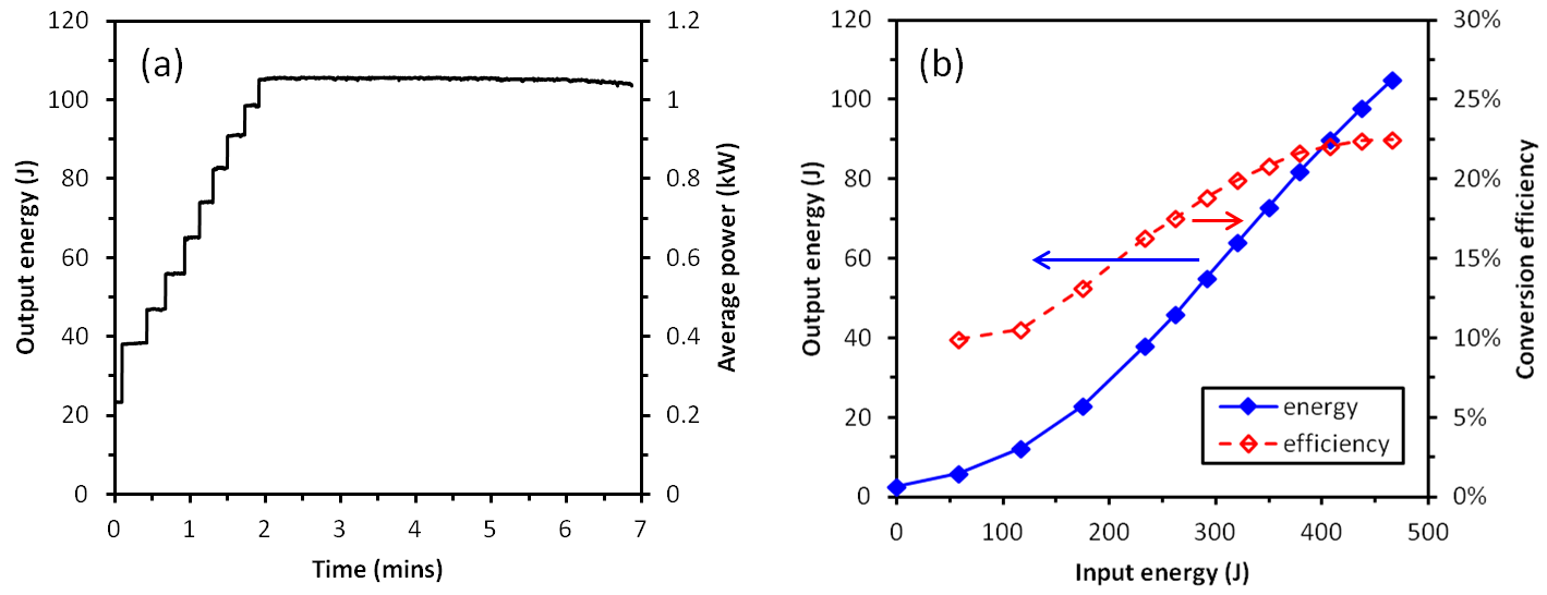
Figure 2(a) shows performance data from the first operating run over 5 minutes at 105 J, 10 Hz clearly showing the energy ramping process. This output energy was achieved at a pump energy of 465 J and operating temperature of 150 K, corresponding to an optical-to-optical conversion efficiency of 22.5%, as seen in Figure 2(b).
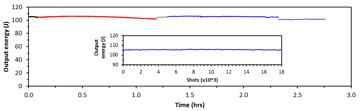
A total of 4.3 × 10^4 shots at energies in excess of 100 J have been completed over a series of runs, with long term energy stability of 1% RMS recorded over a continuous 1-hour period. An example of long-term operation of 100 J laser is shown in Figure 3 below.
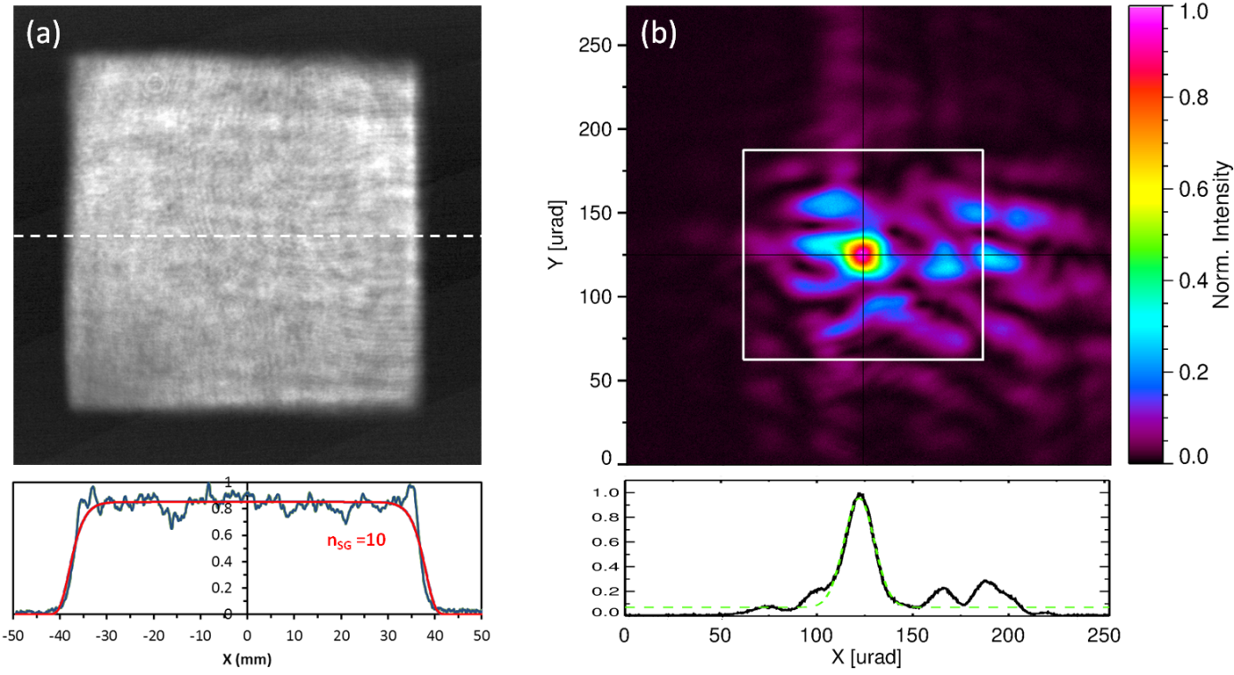
Figure 4(a) shows an output beam profile measured on a diagnostic camera at 102 J and 10 Hz along with a horizontal cross-section taken through the centre of the beam. The red curve is a 10th order super-Gaussian fit to the cross-section data. The circular shaped fringes are artefacts caused by diffraction within the diagnostic channel. An image of the focal spot of the beam captured at maximum output energy is shown in Figure 4(b). The FWHM angular spread of the central maximum was 19 μrad (x-axis) and 20 μrad (y-axis), corresponding to 1.5 and 1.6 times the diffraction limit for a square super-Gaussian beam, respectively. The shape of the deformable mirror was not changed from that determined during 1 Hz seed tests so optimisation may yield further improvement in beam quality.
Team members: Martin Divoký (Team Leader), Jan Pilař, Petr Navrátil, Ondřej Denk, Tomáš Paliesek, Pavel Trojánek